
Effects of Heat Treatment on the Microstructure and Mechanical Properties of a Novel H-Grade Sucker Rod Steel
by
 , and
, and
Zhi Tong
1 ,
,
Guijuan Zhou
1,
Wenyue Zheng
1,*, 
Haining Zhang
2,
Hongyu Zhou
1,* and
Xiaoran Sun
1,2 1
National Center for Materials Service Safety, University of Science and Technology Beijing, Beijing 100083, China
2
Hebei Iron and Steel Group Shi Steel Company, Sports South Street 385, Yuhua District, Shijiazhuang 050023, China
*
Authors to whom correspondence should be addressed.
Metals 2022, 12(2), 294; https://doi.org/10.3390/met12020294
Submission received: 29 December 2021
/
Revised: 24 January 2022
/
Accepted: 28 January 2022
/
Published: 8 February 2022
(This article belongs to the Special Issue Forming and Heat Treatment of Steel)
Abstract
:The sucker rod is an extremely important equipment in oil exploitation, but with the deepening and harsh environment of the petroleum well, higher requirements are put forward for the strength and corrosion resistance of the sucker rod. The most commonly used steel for H grade sucker rods is 4330 steel. However, it has characteristics such as high cost and relatively low sulfide stress cracking resistance. Thus, a novel sucker rod steel with a composition of 0.2 wt.% Cu and 1.2 wt.% Ni was designed. Normalizing + tempering (NT) and quenching + tempering (QT) heat treatment were optimized to render the mechanical properties of the novel sucker rod steel to reach the H grade. Additionally, effects of heat treatment on the microstructural evolution and mechanical properties of the novel sucker rod steel were investigated by optical microscope, scanning electron microscope and mechanical property tests. The results showed that the microstructure is tempered sorbite and the mechanical properties reach H grade after NT and QT. Specifically, the tensile strength, yield strength, elongation and impact toughness of NT/QT samples reached 1010.58/1124.37 MPa, 875.93/1042.63 MPa, 15.66/11.59% and ~77.48/~111.69 J/cm2, respectively. Furthermore, the finer and more dispersed carbides were observed in the QT sample, which means that the QT sample had better strength and toughness.
1. Introduction
Rod-and-pump oil recovery is the most traditional and widely used method of oil and gas development globally [1], and the proportion of oil produced by sucker rod pumping technology in China is as high as 75% [2]. However, with the gradual increase in the number of deep and ultradeep wells in petroleum wells, higher requirements arise for the strength of sucker rod steel. According to tensile strength, sucker rod steel is mainly divided into grades C, K, D, and H [3]. The H grade sucker rod steel is widely used in deep and ultradeep wells with a tensile strength range of 965–1195 MPa. Nevertheless, with the improvement of oil recovery technologies such as wastewater reinjection [4], the environment in which the sucker rod is used has gradually deteriorated, and the corrosiveness (H2S, CO2, etc.) in the well fluid has aggravated the corrosion and failure occurrence of the sucker rod steel [5]. Therefore, the production of oilfields must develop H grade high strength sucker rod steel with excellent performance.
Commonly used for H grade pumping rods, 4330 steel has a medium-carbon and low-alloy design. Considering the progressively harsher oil well environment nowadays, some studies have shown that higher Ni content has a detrimental effect on sulfide stress cracking (SSC) [6,7,8]. The fast-rising cost of Ni also means a high cost of rod steel products. Thus, a novel sucker rod steel needs to be designed, which adjusted the alloy composition based on the original 4330 steel, but with the Ni content controlled to about 1.2 wt.%. On the one hand, such a design may be beneficial to the anti-SSC properties. On the other hand, the content of relatively expensive Ni can be reduced, so that the new composition design can have an economic benefit. Additionally, copper alloying has been reported to have a beneficial effect on steel corrosion [9]. The addition of ≥0.2 wt.% Cu was able to reduce the corrosion of steel and the hydrogen penetration rate in the saturated H2S saturated seawater with a pH of 5 [10], therefore 0.2 wt.% of Cu was added to the new steel. Furthermore, the heat treatment processes were carried out to produce novel H grade high-strength sucker rod steel. Although Al-Maharbi et al. The authors of [11] reported the effects of different heat treatment processes on the mechanical properties of 4330 steel, the specific parameters of the heat treatment were not disclosed due to confidentiality reasons.
Heat treatment is required to obtain the desired microstructure and mechanical properties. Some studies have shown that various heat treatment processes have an important influence on the microstructure and mechanical properties of steel [12,13,14,15]. Normalizing + tempering (NT) or quenching + tempering (QT) heat treatment is one of the most commonly used heat treatment processes due to its convenience and low cost. Fujio has found that the microstructure of F/M steel is composed of tempered martensite, ferrite and large number of precipitates after NT, which directly affects its mechanical properties [16]. QT heat treatment is widely used in various industrial applications, because of its beneficial combination of strength and toughness [17,18,19,20]. Therefore, NT and QT heat treatment are viable choice for the novel sucker rod steel in terms of cost and convenience. However, experiments on NT and QT have not been reported for the novel sucker rod steel. Thus, it is necessary to conduct a detailed study on the effects of NT and QT heat treatment on microstructure and mechanical properties for a novel H grade sucker rod.
In this work, due to the advantages of NT and QT heat treatment processes, heat treatment parameters were designed to make the novel sucker rod steel meet the strength and toughness requirements of H grade sucker rod steel. In addition, the effects of NT and QT on the microstructure and mechanical properties for the novel H grade sucker rod were also studied. These results will provide a reference to the manufacturing, application and promotion of this novel sucker rod steel.
2. Materials and Methods
The experimental steel was taken from a forged billet with dimensions of 160 mm × 160 mm × 235 mm and was rolled into a plate 30 mm thick and 230 mm wide. The chemical composition of the steel investigated is listed in Table 1. It was tested by a direct-reading spectrograph (CX-9800, Wuxi, China). Steel blocks of dimensions 30 mm × 20 mm × 200 mm were then processed from the rolled plate by wire electrical discharge machining for subsequent heat treatment. The heat treatment processes were designed to make the novel steel meet the requirements of H grade according to GB/T 26075-2010 standard [3], and the specific parameters are shown in Table 2 (Muffle furnace, Changsha, China). For convenience, the samples after normalizing and quenching of 880 and 860 °C are designated N and Q respectively. The samples after normalizing + tempering and quenching + tempering are named NT and QT, respectively. Besides, the JMatPro software (V 11.0, Sente Software, Guildford, UK) was used to calculate the CCT (continuous cooling transformation) curve of experimental steel in order to analyze the behavior of different cooling methods.
Samples for microstructure characterization were prepared by wire cut electrical discharge machining. Then these samples were ground by 400 to 2000 grit silicon carbide papers under running water and polished by diamond polishing paste of W2.5. After that, all the samples were etched with 4 vol % nital solution. The microstructural examinations of the samples were conducted using an optical microscope (OM, POLYVAR-MET, Oberkochen, Germany) and scanning electron microscope (SEM, Zeiss Merlin Compact, Oberkochen, Germany).
After the heat treatments, mechanical properties were determined by performing tensile tests (Tensile testing machine, CM75105, Xian, China) and Charpy impact tests (Impact testing machine, JBDW-300D, Jinan, China) at room temperature. Tensile samples were prepared according to GB/T 228–2010 [21]. And the half-size U-notch impact specimens were prepared for Charpy impact tests with dimensions 5 mm × 10 mm × 55 mm at room temperature. Finally, the tensile and impact fracture surface were observed by SEM and analyze precipitates with the energy dis-pensive X-ray spectrum (EDS).
3. Results and Discussion
3.1. Microstructure Analysis
After austenitizing, the experimental steel was cooled to room temperature by air cooling and water cooling, which are called normalizing and quenching, respectively. The microstructures of experimental steel after normalizing and quenching were observed by OM and SEM, as shown in Figure 1. The microstructure of the as-normalized sample consisted of granular bainite (GB) and a small amount of martensite with a volume fraction of about 5% (Figure 1a) with grain size ~25.61 μm by Nano Measure software (Shanghai, China, a software to measure length according to the scale; the grain size is the average grain diameter). The small amount of martensite (~5 vol. %) in Figure 1a was mainly due to some alloying elements segregated during the rolling process. During the continuous cooling process, the hardenability of this region was improved, resulting in the formation of martensite. Small-sized (<1 μm) MA (martensite-austenite) constituents were uniformly distributed in parallel on the bainitic ferrite matrix and banded or blocky MA constituents were formed along the PAGBs (prior austenite grain boundaries). No obvious carbides were observed, as shown in Figure 1b. The microstructure of the as-quenched sample was a full martensite structure (Figure 1c), and the grain size was about 24.01 μm, slightly smaller than the normalized state. A prior austenite grain was composed of about 3~4 martensite packets, as shown in Figure 1d.
To analyze the influence of cooling methods (WC and AC) and behavior during the cooling process, the CCT curve of the sample was calculated by JMatPro software (a software for metal thermodynamic calculations) and is shown in Figure 2. The comparison of the WC and AC curves in Figure 2 indicates that the WC is the area of full martensite, and the value of the water-cooling rate was much greater than 100 °C/s, while the AC was in the region of bainite. Therefore, the test steel was fully martensite after water cooling and had a granular bainite structure after air cooling. The martensite formed after quenching was mainly composed of martensite laths. There is a large number of dislocation substructures in lath martensite [22], and the bainite structure after normalizing is composed of ferrite matrix and part of MA. Additionally, no significant difference was observed in the prior austenite grain size due to the similar austenitization temperature between normalizing and quenching (~20 °C) treatments.
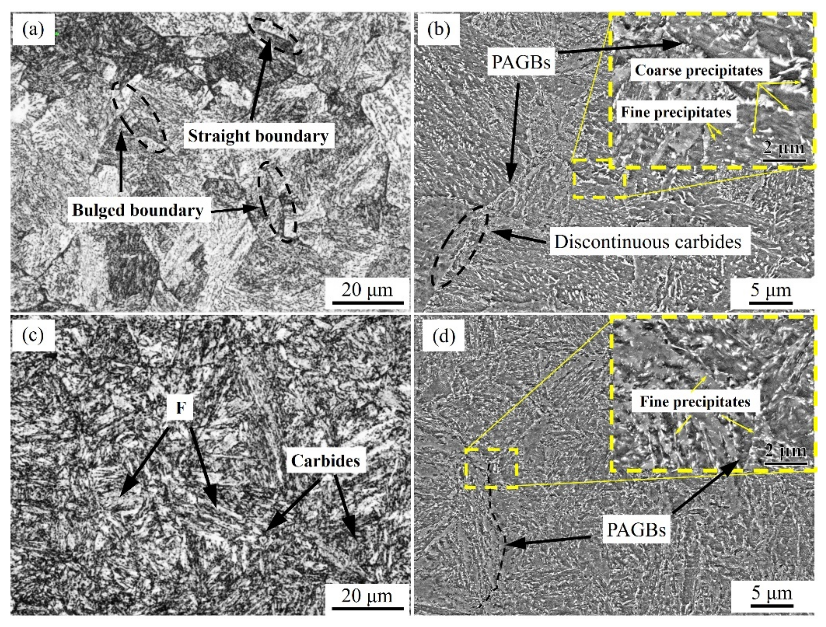
The microstructures of NT and QT samples were studied to investigate the microstructure evolution using OM and SEM, as shown in Figure 3. From Figure 3a, it can be observed that the microstructure of the NT sample was tempered sorbite, which was mainly composed of ferrite matrix and precipitated phases. A straight boundary and bulged boundary were clearly visible, and the ferrite matrix was blocky. The precipitates in the ferrite matrix were distributed in the prior normalized MA constituents’ orientation (Figure 1a,b). The morphology of the NT sample is shown in Figure 3b, and the higher magnification SEM micrograph is shown in the top right corner. After tempering, the MA that formed in the bulk or grain boundary during normalizing was transformed into carbide precipitates. The area where the prior MA existed at the grain boundary and bulk was mainly coarse precipitate, while a small number of fine precipitates were inside the matrix area (Figure 3b). Discontinuous strips or blocky carbides were observed at grain boundaries, as shown in Figure 3b. The microstructure of the QT sample was tempered sorbite composed of ferrite matrix and carbides, as shown in Figure 3c. In contrast, the grain boundaries in the tempered sorbite of the QT sample were no longer clearly visible. The ferrite matrix was distributed in strips and retains the orientation relationship of the prior martensite lath. The precipitates in the ferrite matrix were mainly distributed in the orientation of the prior quenched lath martensite (Figure 1c,d). The morphology of QT is shown in Figure 3d, and the high magnification SEM micrograph is shown in the top right corner. After tempering, the carbides were mainly distributed in spherical discontinuities at the prior martensite lath and packet interface or grain boundary, which were relatively coarse and have a small amount of fine carbides in bulk, as shown in Figure 3d. Unlike the NT sample, the carbides were mainly distributed at the prior martensite lath boundaries, with finer dimensions and larger quantities.
3.2. Tensile Property and Fractographic Analysis
The engineering tensile stress-strain curves of NT and QT are shown in Figure 4. The NT samples had a tensile strength (Rm) of ~1010.58 MPa, a yield strength (Rp0.2) of ~875.93 MPa and an elongation (A) of ~15.66%. The corresponding values of the QT samples were ~1124.37 MPa, ~1042.63 MPa and 11.59%, respectively. The tensile properties of H grade sucker rod were required for Rm-965.00~1195.00 MPa, Rp0.2 ≥ 795.00 MPa and A ≥ 10.00% according to GB/T 26075-2010 standard [3]. It can be seen that the tensile properties of NT and QT samples all meet the requirements of H grade sucker rod steel. However, the strength of the NT samples was significantly reduced at the same tempering temperature. The Rm and Rp0.2 values of NT were about ~113.79 MPa and ~166.70 MPa lower than QT. Nevertheless, compared with QT the elongation of NT was improved by 4.07%.
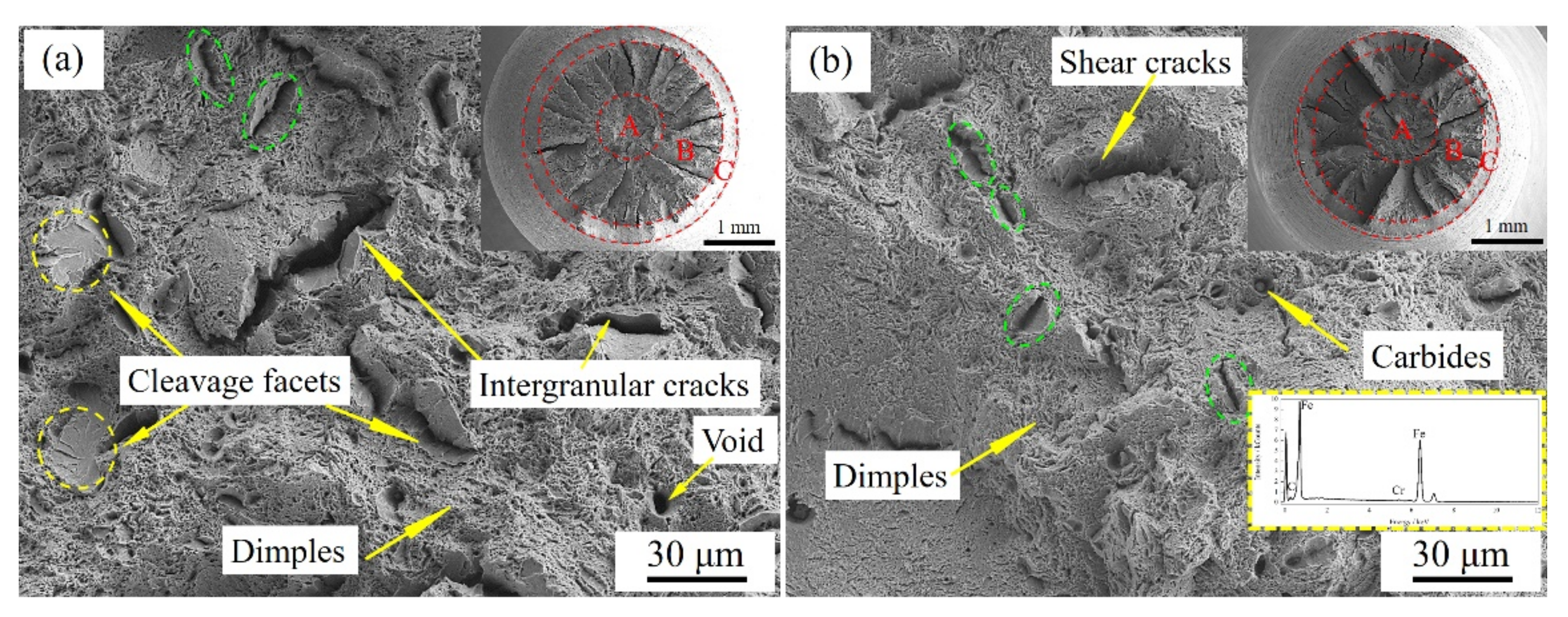
A clear neck shrinkage was found in the fractured tensile sample. Figure 5 shows typical ductile tensile fracture surfaces of NT and QT samples. Area A is the fiber area in the center, which is the location of fracture initiation, and this area reflects the tensile properties of the material [23]. The central fiber area of the NT samples is shown in Figure 5a. The fracture surface was mainly ductile dimples formed by the merger of micropores in the microstructure, but there were a number of secondary cracks. Large intergranular fracture cracks (length >30 μm) were observed in some areas, and partial cleavage fractures appeared near the secondary cracks. The central fiber area of the QT sample is shown in Figure 5b. The fracture surface was mainly ductile dimples. The size of dimples was obviously smaller, but the depth was significantly greater than that of the NT sample. Generally, the size of the dimple is related to the size of the carbide. The deeper the dimple, the greater the energy consumed in the fracture process [24]. There were some spherical carbides in the dimples, which were analyzed to be Cr-rich carbides by EDS. This was mainly due to the nucleation of microvoids on the carbide particles, which eventually form fracture initiation pit sites. Meanwhile, there are some secondary cracks in the QT sample with a small size and no obvious intergranular cracks on the main surface were found, but a small number of shear cracks were found perpendicular to the fracture surface in the central fracture area, as shown in Figure 5b.
The microstructure change directly affects the strength of the material, and the strengthening mechanism of tempered steel is mainly through the following mechanisms: solid solution strengthening, dislocation strengthening, grain boundary strengthening, and precipitation strengthening. First, solid solution strengthening mainly depends on the composition of alloy elements (Mn, Si, Ni, Mo) in the steel [25]. Since the heat treatment process did not change the chemical composition of the experimental steel, it can be considered that the contribution of solid solution strengthening was similar for the different types of samples. As for grain boundary strengthening, the NT and QT samples had similar austenitizing temperatures and similar final prior austenite grain sizes, resulting in similar grain boundary strengthening contributions. Although Krauss suggested that martensitic lath can be considered as an effective grain [26], the contribution of martensite lath to strength is mainly due to the carbides and dislocations in martensite lath [27]. Therefore, the principal strengthening effect observed in the QT and NT samples mainly derived from dislocation and precipitation strengthening.
Nevertheless, the experimental steel after quenching has a martensite structure. Generally, there are a large number of dislocations in martensite lath [22]. During the subsequent tempering process, although some dislocations recovered, a large number of dislocations still existed in the ferrite matrix, which means that there was a higher dislocation density in the QT sample, and the dislocation strengthening was more dominant than the NT sample.
The effect of precipitation strengthening can be expressed according to the Ashby–Orowan equation as follows [28]:
where G is the shear modulus, fp is the volume fraction of precipitates, dp is the diameter of precipitates and b is the Burgers vector. In this study, the G and b of NT and QT samples were equal, so the precipitation strengthening depended on the size (dp) and volume fraction of the precipitates (fp). In other words, the smaller the precipitate size and the greater the degree of dispersion, the stronger the strengthening effect.
The microstructure of the Q sample was martensite with a large number of laths, which were the preferential nucleating sites during tempering subsequently. Therefore, the carbides in the QT sample were finer and more dispersed than those in the NT sample due to the abundance of nucleating sites, resulting in a better strengthening effect. In summary, the QT sample had a higher dislocation density and more dispersed fine precipitates, which led to higher tensile strength.
3.3. Impact Toughness and Fractographic Analysis
The impact toughness of the NT and QT samples at room temperature was 77.48 ± 3.21 J/cm2 and 111.69 ± 2.28 J/cm2, respectively. The values of impact toughness met the qualification of H grade sucker rod steel of 60 J/cm2. In general, samples with higher tensile properties have correspondingly lower impact toughness, which can be seen in many materials [29]. However, for the novel sucker rod steel in this study, the QT sample had a higher tensile strength of Rm ~1124.37 MPa and had better room temperature impact toughness of Ku2 ~111.69 J/cm2.
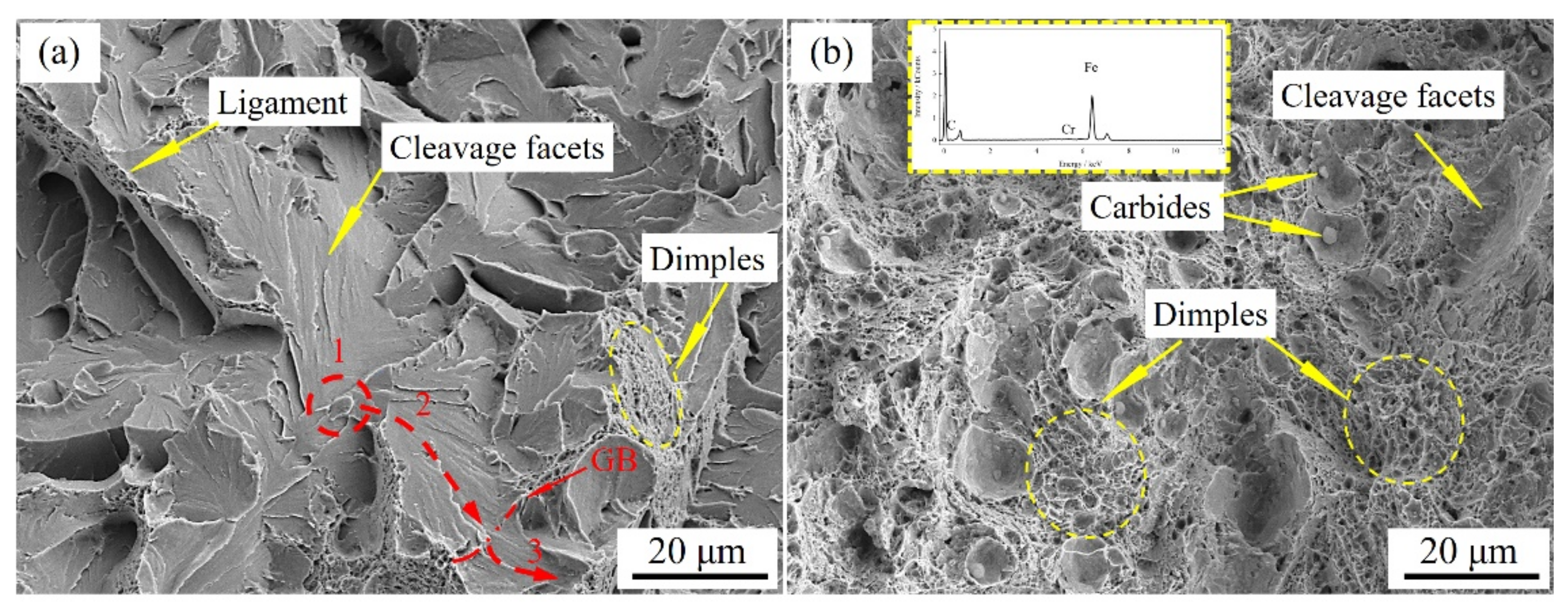
The toughness of steel mainly depends on the ability to absorb energy during deformation and fracture that is the ability to resist crack formation and propagation [30]. The fracture surfaces of NT and QT samples are shown in Figure 6. The NT sample fracture mode was mainly composed of cleavage fracture and a small amount of ligaments. The crack nucleus initiated at a crack in the carbide particle at the grain boundary. The crack 2, finally entered grain 3 along grain 2. The fracture mode of the QT sample was a mainly ductile fracture with many dimples and some residual carbide particles in the center of the dimples. It was confirmed by EDS to be Cr-rich carbides, and there were a small number of cleavage fractures.
The main way to improve the toughness of a steel is to refine its grain structure. For the NT and QT samples in this study, the austenitizing temperature was similar, so the grain size was similar. However, the microstructure of the QT sample after quenching was lath martensite. Luo et al. [31] proposed that the martensite block can be considered an effective unit for controlling fracture toughness. After subsequent tempering, the prior martensite lath and blocks are still partially inherited. Therefore, the block size in the QT sample was the effective grain size for controlling toughness. The block size in martensite was much smaller than the prior austenite grain size, which greatly improves the fracture toughness of the QT sample. On the other hand, as shown by the impact fracture of Figure 6, the most significant influence on the impact toughness of the steel was the carbide near the interface. The intergranular and transgranular fracture in the steel is closely related to the carbide along the PAGB and lath boundary [32]. The impact toughness of steel materials largely depends on the initiation of cracks and subsequent crack propagation [30]. According to Griffith’s theory [33], the size of carbide particles exceeding the critical size (rc) given by Equation (2) can result in cleavage fracture.
where rc is the critical stress of crack propagate/on, E is Young’s modulus, γp is the effective surface energy and the ν is the Poisson ratio. Lee et al. [34] calculated the critical carbide size of Cr-Ni-Mo steel under high temperature tempering according to Equation (2) to be 150 nm, that is, when the carbide size is larger than 150 nm, it will cause cleavage fracture. Since the precipitation behaviour of carbides inherited prior MA at the grain boundary, the size of carbides was larger than 150 nm in the NT sample (Figure 3b). Therefore, it can be reasonably stated that the poor impact toughness of the NT sample can be attributed to its larger carbides.
The microstructure and mechanical properties of NT and QT samples may have changed remarkably during tempering, and these changes are influenced by initial normalized and quenched microstretches. Generally, the precipitation and coarsening of the carbides occur mainly during tempering rather than during normalizing or quenching. The microstructure is granular bainite after normalizing, and the decomposition of MA and softening of bainite ferrite occur during tempering and the synergistic effect between these two processes determines the strength and impact toughness [35].
4. Conclusions
In summary, NT and QT heat treatment manufacturing processes were utilized to make the mechanical properties of the novel sucker rod steel reach H grade requirements. The microstructure and mechanical properties of the experimental steel were comparatively investigated. Several conclusions can be given as follows:
- The microstructure of normalizing and quenching was granular bainite and lath martensite, respectively. After tempering at 600 °C, the microstructure of NT and QT samples was tempered sorbite. The ferrite matrix was blocky or polygonal, and the large size carbides were distributed in the MA/ferrite matrix interfaces and grain boundaries after NT heat treatment. The ferrite matrix inherited the prior martensite lath structure after QT heat treatment. The size of carbides at grain boundaries or the interface of martensite laths was smaller and the degree of dispersion was higher.
- Through N (880 °C) + T (600 °C) and Q (860 °C) + T (600 °C) heat treatment processes, the mechanical properties of the novel sucker rod steel met the requirements of GB/T 26075-2010. Specifically, the tensile strength (Rm), yield strength (Rp0.2), elongation (A) and impact toughness (Ku2) at room temperature of NT/QT were 1010.58/1124.37 MPa, 875.93/1042.63 MPa, 15.66/11.59% and ~77.48/~111.69 J/cm2, respectively. During tensile loading, the finer and more dispersed carbides in the QT sample provided the abundant nucleating sites, resulting in a better strengthening effect shown as the higher tensile strength.
- N (880 °C) + T (600 °C) and Q (860 °C) + T (600 °C) heat treatment are suitable processes for manufacturing H grade novel sucker rod steel. This study will provide a reference for the manufacturing, application and promotion of this novel sucker rod steel.
Author Contributions
Conceptualization, Z.T. and W.Z.; methodology, Z.T.; software, G.Z.; formal analysis, G.Z., H.Z. (Hongyu Zhou) and H.Z. (Haining Zhang); investigation, Z.T., G.Z., X.S. and H.Z. (Hongyu Zhou); resources, X.S., W.Z. and H.Z. (Hongyu Zhou); writing—original draft preparation, Z.T. and G.Z.; writing—review and editing, W.Z. and H.Z. (Hongyu Zhou); supervision, W.Z. and H.Z. (Hongyu Zhou); funding acquisition, W.Z. and H.Z. (Hongyu Zhou). All authors have read and agreed to the published version of the manuscript.
Funding
This research was funded by Beijing Municipal Science and Technology Commission, grant number Z201100004520011.
Institutional Review Board Statement
Not applicable.
Informed Consent Statement
Not applicable.
Data Availability Statement
Not applicable.
Acknowledgments
Thanks are due to Hebei Iron and Steel Group Shi Steel Company for providing experimental steels in this study.
Conflicts of Interest
The authors declare no conflict of interest.
References
- Takacs, G. Sucker-rod pumping system components and their operation. In Sucker-Rod Pumping Handbook, 3rd ed.; Gulf Professional Publishing: Houston, TX, USA, 2015; pp. 57–246. [Google Scholar]
- Zhongying, H.; Xiaoguang, H. Investigations on corrosion behaviors of super-strength sucker rod FG20 steel in high SO42− environment. J. Mater. Res. Technol. 2019, 8, 788–794. [Google Scholar] [CrossRef]
- GB/T 26075-2010; Steel Bars for Sucker Rods. China Standard Press: Beijing, China, 2010.
- Sugai, Y.; Sasaki, K.; Wakizono, R.; Higuchi, Y.; Muraoka, N. Considerations on the possibility of microbial clogging of re-injection wells of the wastewater generated in a water-dissolved natural gas field. Int. Biodeter. Biodegr. 2013, 81, 35–43. [Google Scholar] [CrossRef]
- Duan, D.L.; Geng, Z.; Jiang, S.L.; Li, S. Failure mechanism of sucker rod coupling. Eng. Fail. Anal. 2014, 36, 166–172. [Google Scholar] [CrossRef]
- Koval, V.P.; Karvatskii, L.M.; Koval’Chuk, R.I. Influence of carbon, nickel, manganese, and vanadium on stress-corrosion cracking of steels in a medium containing hydrogen sulfide. Mater. Sci. 1979, 15, 161–164. [Google Scholar] [CrossRef]
- Yoshino, Y.; Minozaki, Y. Sulfide stress cracking resistance of low-alloy nickel steels. Corrosion 1986, 42, 222–233. [Google Scholar] [CrossRef]
- Treseder, R.S.; Swanson, T.-M. Factors in sulfide corrosion cracking of high strength steel. Corrosion 1968, 24, 31–37. [Google Scholar] [CrossRef]
- Samusawa, I.; Nakayama, S. Influence of plastic deformation and Cu addition on corrosion of carbon steel in acidic aqueous solution. Corros. Sci. 2019, 159, 108122. [Google Scholar] [CrossRef]
- Mendibide, C.; Sourmail, T. Composition optimization of high-strength steels for sulfide stress cracking resistance improvement. Corros. Sci. 2009, 51, 2878–2884. [Google Scholar] [CrossRef]
- Al-Maharbi, M.; Al-Shabibi, A.; Qamar, S.-Z. Manufacturing of low alloy steel sucker rods by continuous process—Heat treatment and characterization. Mater. Manuf. Process. 2018, 33, 1889–1893. [Google Scholar] [CrossRef]
- Ríos-Diez, O.; Aristizábal-Sierra, R.; Serna-Giraldo, C.; Jimenez, J.A.; Garcia-Mateo, C. Development of nanobainitic microstructures in carbo-austempered cast steels: Heat treatment, microstructure and properties. Metals 2020, 10, 635. [Google Scholar] [CrossRef]
- Mazuro, P.; Pieńkowska, J.; Rostek, E. Influence of various heat treatments on hardness and impact strength of uddeholm Balder: Cr-Mo-V-Ni novel steel used for engine construction. Materials 2021, 14, 4943. [Google Scholar] [CrossRef]
- Kandpal, B.-C.; Gupta, D.-K.; Kumar, A.; Ashish, K.-J.; Ranjan, A.-K.; Srivastava, A.; Chaudhary, P. Effect of heat treatment on properties and microstructure of steels. Mater. Today Proc. 2021, 44, 199–205. [Google Scholar] [CrossRef]
- Singh, G. A review on effect of heat treatment on the properties of mild steel. Mater. Today Proc. 2021, 37, 2266–2268. [Google Scholar] [CrossRef]
- Fujio, A. Precipitate design for creep strengthening of 9% Cr tempered martensitic steel for ultra-supercritical power plants. Technol. Adv. Mater. 2008, 9, 013002. [Google Scholar] [CrossRef] [Green Version]
- Zheng, Y.-X.; Wang, F.-M.; Li, C.-R.; Li, Y.-L.; Cheng, J.; Cao, R.-F. Effect of microstructure and precipitates on mechanical properties of Cr–Mo–V alloy steel with different austenitizing temperatures. ISIJ Int. 2018, 58, 1126–1135. [Google Scholar] [CrossRef] [Green Version]
- Cheng, X.-Y.; Zhang, H.-X.; Li, H.; Shen, H.-P. Effect of tempering temperature on themicrostructure and mechanical properties in mooring chain steel. Mater. Sci. Eng. A 2015, 636, 164–171. [Google Scholar] [CrossRef]
- Yan, Z.-J.; Liu, K.; Eckert, J. Effect of tempering and deep cryogenic treatment on microstructure and mechanical properties of Cr–Mo–V–Ni steel. Mater. Sci. Eng. A. 2020, 787, 139520. [Google Scholar] [CrossRef]
- Basori, I.; Surocaena, A.; Dwiyati, S.-T.; Sari, Y.; Singh, B. Microstructure and mechanical properties analysis of quenched and tempered aisi 4340 steel. KnE Soc. Sci. 2019, 3, 675–680. [Google Scholar] [CrossRef]
- GB/T 228-2010; Metallic Materials-Tensile Testing-Part 1: Method of Test at Room Temperature. China Standard Press: Beijing, China, 2010.
- Sun, D.J.; Guo, Z.H.; Gu, J.F. The microstructure and crystallography of lath martensite with Greninger-Troiano orientation relationship in a Fe-12.8Ni-1.5Si-0.22%C steel. Mater. Charact. 2021, 181, 111501. [Google Scholar] [CrossRef]
- Kao, A.S.; Kuhn, H.A.; Richmond, O.; Spitzig, W.-A. Tensile fracture and fractographic analysis of 1045 spheroidized steel under hydrostatic pressure. J. Mater. Res. 1990, 5, 83–91. [Google Scholar] [CrossRef]
- Chen, K.; Jiang, Z.H.; Liu, F.B.; Yu, J.; Li, Y.; Gong, W.; Chen, C.Y. Effect of quenching and tempering temperature on microstructure and tensile properties of microalloyed ultra-high strength suspension spring steel. Mater. Sci. Eng. A 2019, 766, 138272. [Google Scholar] [CrossRef]
- An, F.C.; Wang, J.J.; Zhao, S.X.; Liu, C.M. Tailoring cementite precipitation and mechanical properties of quenched and tempered steel by nickel partitioning between cementite and ferrite. Mater. Sci. Eng. A 2021, 802, 140686. [Google Scholar] [CrossRef]
- Krauss, G. Martensite in steel: Strength and structure. Mater. Sci. Eng. A 1999, 273–275, 40–57. [Google Scholar] [CrossRef]
- Tomita, Y.; Okabayashi, K. Effect of microstructure on strength and toughness of heat-treated low alloy structural steels. Metall. Trans. A 1986, 17, 1203–1209. [Google Scholar] [CrossRef]
- Shang, Z.; Ding, J.; Fan, C.; Song, M.; Li, J.; Li, Q.; Xue, S.; Hartwig, K.-T.; Zhang, X. Tailoring the strength and ductility of T91 steel by partial tempering treatment. Acta Mater. 2019, 169, 209–224. [Google Scholar] [CrossRef]
- Watanabe, K.; Kawasaki, T.; Tanaka, H. Structural origin of enhanced slow dynamics near a wall in glass-forming systems. Nat. Mater. 2011, 10, 512–520. [Google Scholar] [CrossRef]
- Jiang, Z.; Wang, P.; Li, D.; Li, Y. The evolutions of microstructure and mechanical properties of 2.25Cr-1Mo-0.25V steel with different initial microstructures during tempering. Mater. Sci. Eng. A 2017, 699, 165–175. [Google Scholar] [CrossRef]
- Luo, Z.J.; Shen, J.C.; Su, H.; Ding, Y.H.; Yang, C.F.; Zhu, X. Effect of substructure on toughness of lath martensite-bainite mixed structure in low-carbon steels. J. Iron Steel Res. Int. 2010, 17, 40–48. [Google Scholar] [CrossRef]
- Li, H.F.; Duan, Q.Q.; Zhang, P.; Zhang, Z.-F. The relationship between strength and toughness in tempered steel: Trade-off or invariable? Adv. Eng. Mater. 2019, 21, 1801116. [Google Scholar] [CrossRef]
- Yan, C.; Chen, J.; Sun, J.; Wang, Z. Critical assessment of the local cleavage stress σ * in notch specimens of C-Mn steel. Metall. Mater. Trans. A. 1993, 24, 1381–1389. [Google Scholar] [CrossRef]
- Lee, K.; Park, S.; Kim, M.; Lee, B.; Wee, D. Characterization of transition behavior in SA508 Gr.4N Ni–Cr–Mo low alloy steels with microstructural alteration by Ni and Cr contents. Mater. Sci. Eng. A 2011, 529, 156–163. [Google Scholar] [CrossRef]
- Jiang, Z.; Wang, P.; Li, D.; Li, Y. Effect of tempering temperature on the microstructure and mechanical properties of granular bainite in 2.25Cr-1Mo-0.25V steel. Acta Metall. Sin. 2015, 51, 925–934. [Google Scholar] [CrossRef]
Figure 1.
Microstructure of as-normalized and as-quenched. (a,b) OM and SEM images of normalizing; (c,d) OM and SEM images of quenching. GB: granular bainite, M: martensite, MA: martensite-austenite constituent, PAGB: prior austenite grain boundary.
Figure 1.
Microstructure of as-normalized and as-quenched. (a,b) OM and SEM images of normalizing; (c,d) OM and SEM images of quenching. GB: granular bainite, M: martensite, MA: martensite-austenite constituent, PAGB: prior austenite grain boundary.

Figure 2.
CCT curves of the sucker rod steel calculated by the JMatPro software.

Figure 3.
OM and SEM images of (a,b) NT and (c,d) QT. The tallow dashed box in the upper right corner of (b,d) is a partially enlarged detail image. PAGBs: prior austenite grain boundaries.
Figure 3.
OM and SEM images of (a,b) NT and (c,d) QT. The tallow dashed box in the upper right corner of (b,d) is a partially enlarged detail image. PAGBs: prior austenite grain boundaries.

Figure 4.
The engineering tensile stress-strain curves of NT and QT samples.

Figure 5.
SEM micrographs of the fracture surface A area (in the upper right corner) of tensile samples. (a) NT; (b) QT. A: fiber region, B: radial region, C: shear lip. The green dashed frame is the secondary crack.
Figure 5.
SEM micrographs of the fracture surface A area (in the upper right corner) of tensile samples. (a) NT; (b) QT. A: fiber region, B: radial region, C: shear lip. The green dashed frame is the secondary crack.

Figure 6.
SEM micrographs of the fracture surface of impact samples, (a) NT; (b) QT. 1: grain 1; 2: grainn 2; 3: grain 3.
Figure 6.
SEM micrographs of the fracture surface of impact samples, (a) NT; (b) QT. 1: grain 1; 2: grainn 2; 3: grain 3.


Table 1.
Chemical composition of the experimental steel (wt.%).
| C | Si | Mn | Cr | Ni | Mo | V | Ti | Cu | P | S | Fe |
|---|---|---|---|---|---|---|---|---|---|---|---|
| 0.30 | 0.25 | 0.88 | 0.84 | 1.23 | 0.25 | 0.088 | 0.005 | 0.188 | 0.0088 | 0.005 | Bal. |
Table 2.
The heat treatment protocol of experimental steel. (AC: air cooling, WC: water cooling).
| Sample No. | Austenitizing/°C (for 55 min) | Cooling Method | Tempering/°C (for 67 min) | Cooling Method |
|---|---|---|---|---|
| N | 880 | AC | - | - |
| Q | 860 | WC | ||
| NT | 880 | AC | 600 | AC |
| QT | 860 | WC |
Publisher’s Note: MDPI stays neutral with regard to jurisdictional claims in published maps and institutional affiliations. |
© 2022 by the authors. Licensee MDPI, Basel, Switzerland. This article is an open access article distributed under the terms and conditions of the Creative Commons Attribution (CC BY) license (https://creativecommons.org/licenses/by/4.0/).
Share and Cite
MDPI and ACS Style
Tong, Z.; Zhou, G.; Zheng, W.; Zhang, H.; Zhou, H.; Sun, X. Effects of Heat Treatment on the Microstructure and Mechanical Properties of a Novel H-Grade Sucker Rod Steel. Metals 2022, 12, 294. https://doi.org/10.3390/met12020294
AMA Style
Tong Z, Zhou G, Zheng W, Zhang H, Zhou H, Sun X. Effects of Heat Treatment on the Microstructure and Mechanical Properties of a Novel H-Grade Sucker Rod Steel. Metals. 2022; 12(2):294. https://doi.org/10.3390/met12020294
Chicago/Turabian StyleTong, Zhi, Guijuan Zhou, Wenyue Zheng, Haining Zhang, Hongyu Zhou, and Xiaoran Sun. 2022. "Effects of Heat Treatment on the Microstructure and Mechanical Properties of a Novel H-Grade Sucker Rod Steel" Metals 12, no. 2: 294. https://doi.org/10.3390/met12020294
Note that from the first issue of 2016, this journal uses article numbers instead of page numbers. See further details here.