
Scaling up the Fabrication of Mechanically-Robust Carbon Nanofiber Foams

 and
and
Abstract
:1. Introduction
2. Experimental Section
2.1. Carbon Nanofiber Foam Growth
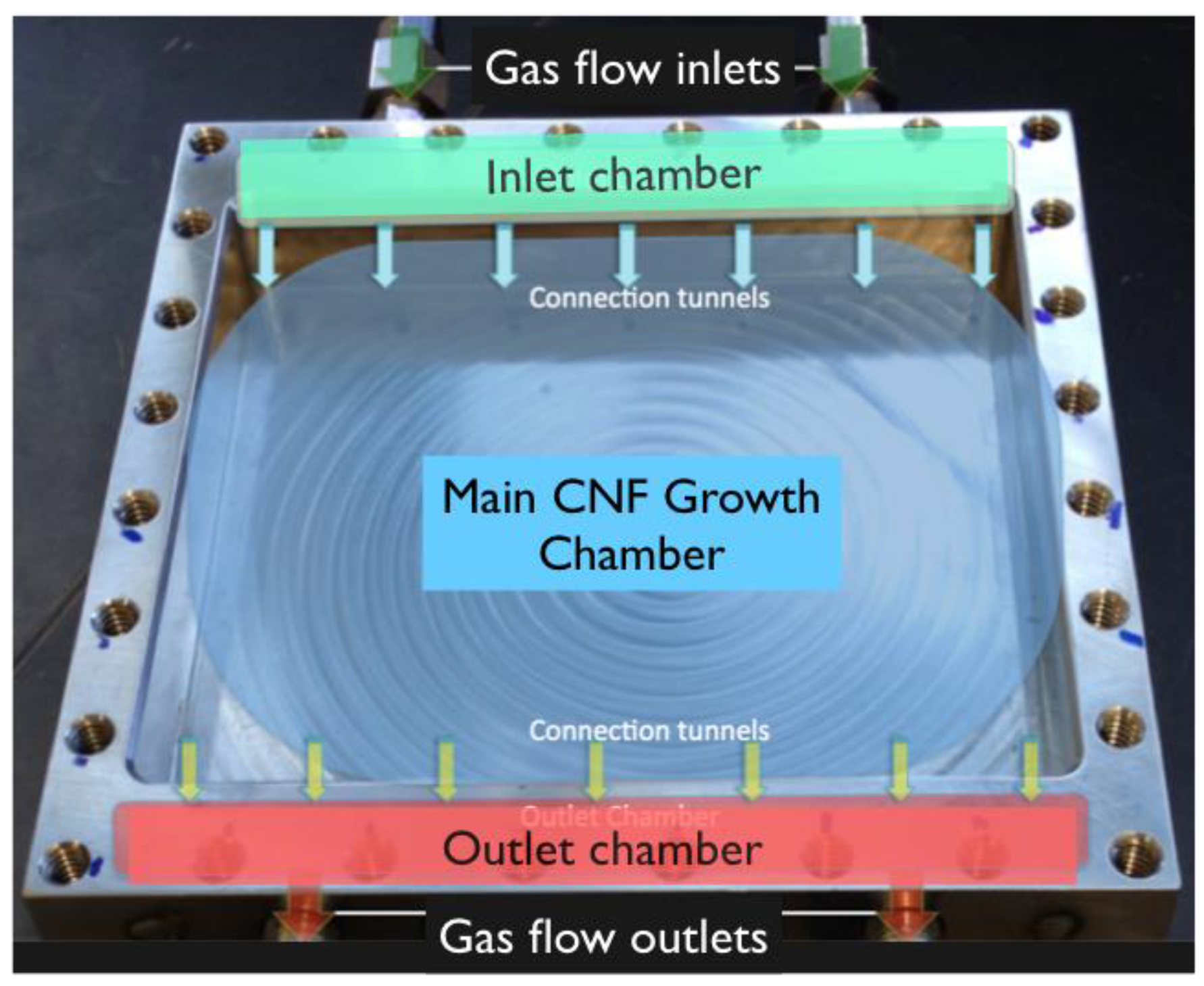
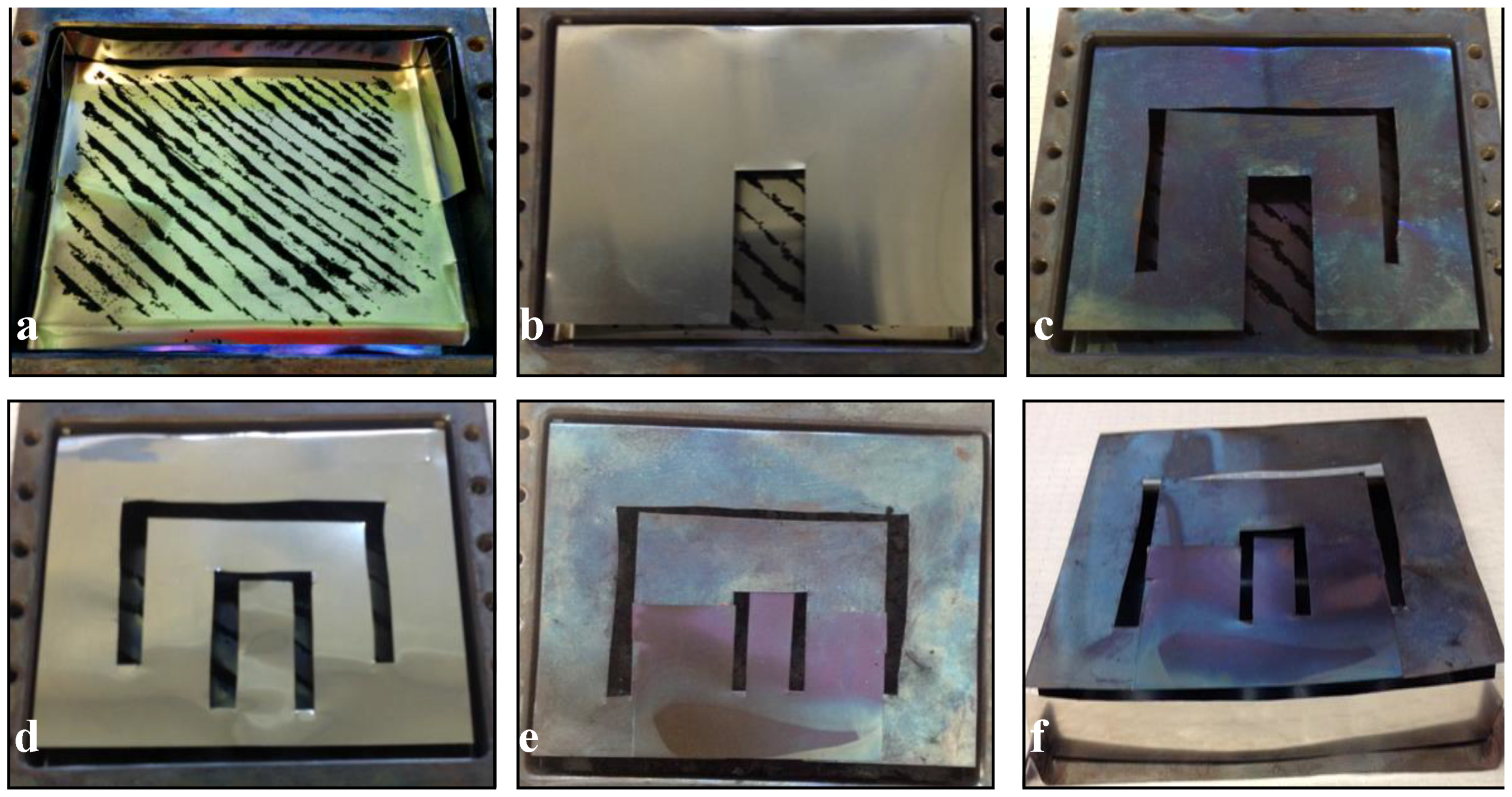
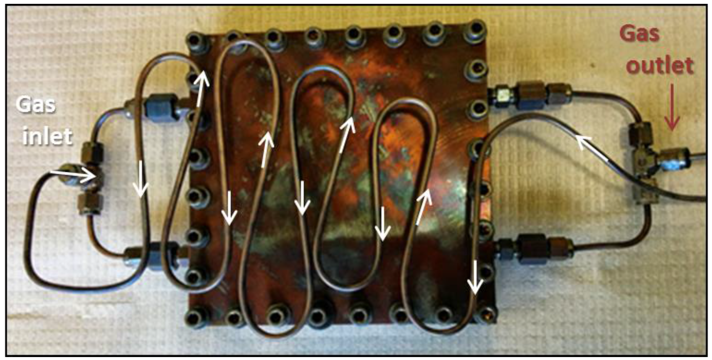
2.2. Mold-Lid Construction and Deflector Material


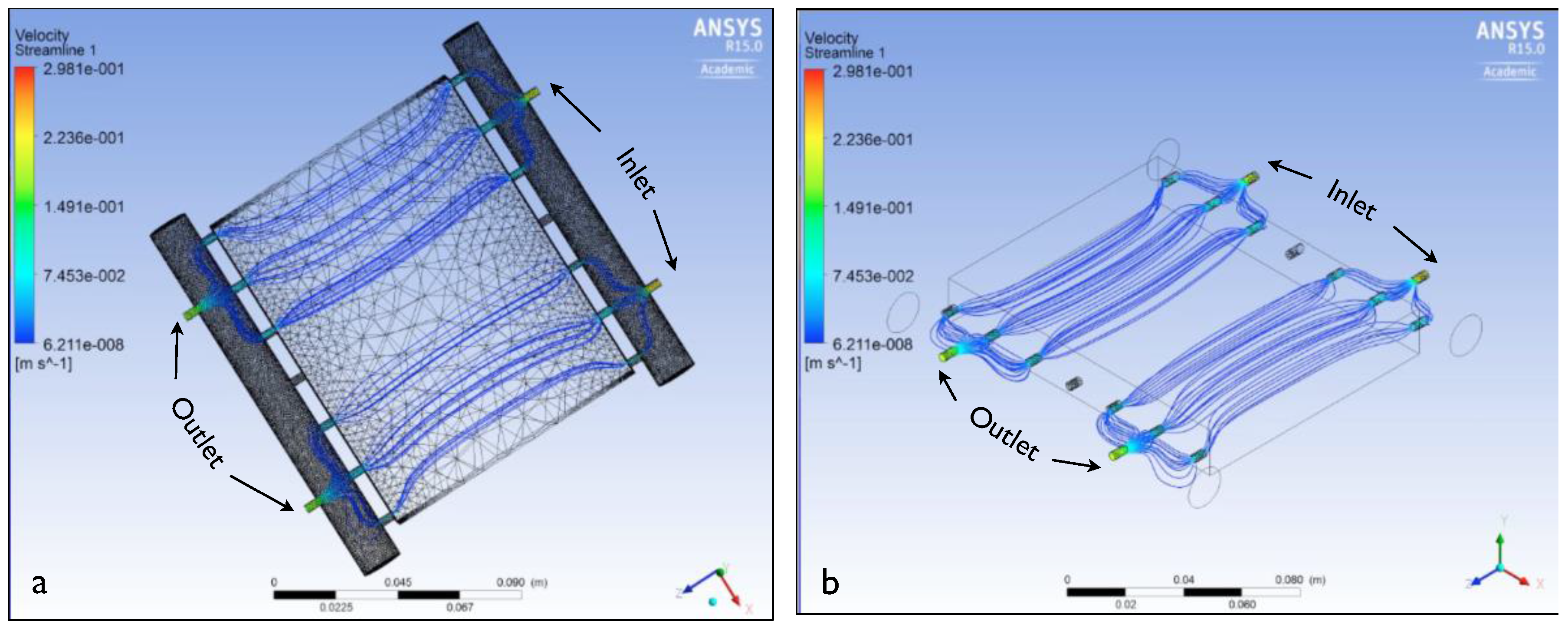
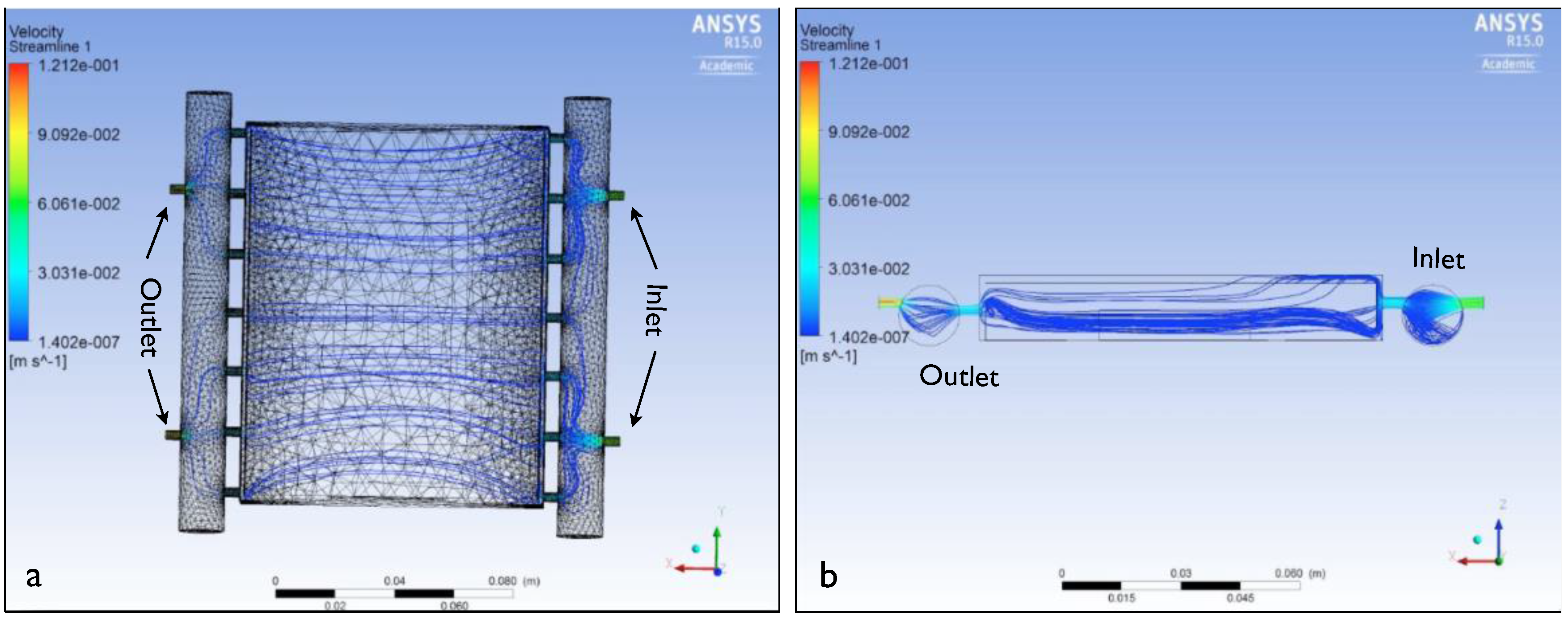
2.3. ANSYS Modeling
2.4. Palladium Catalyst Recovery
2.5. Characterization Techniques
3. Results and Discussion
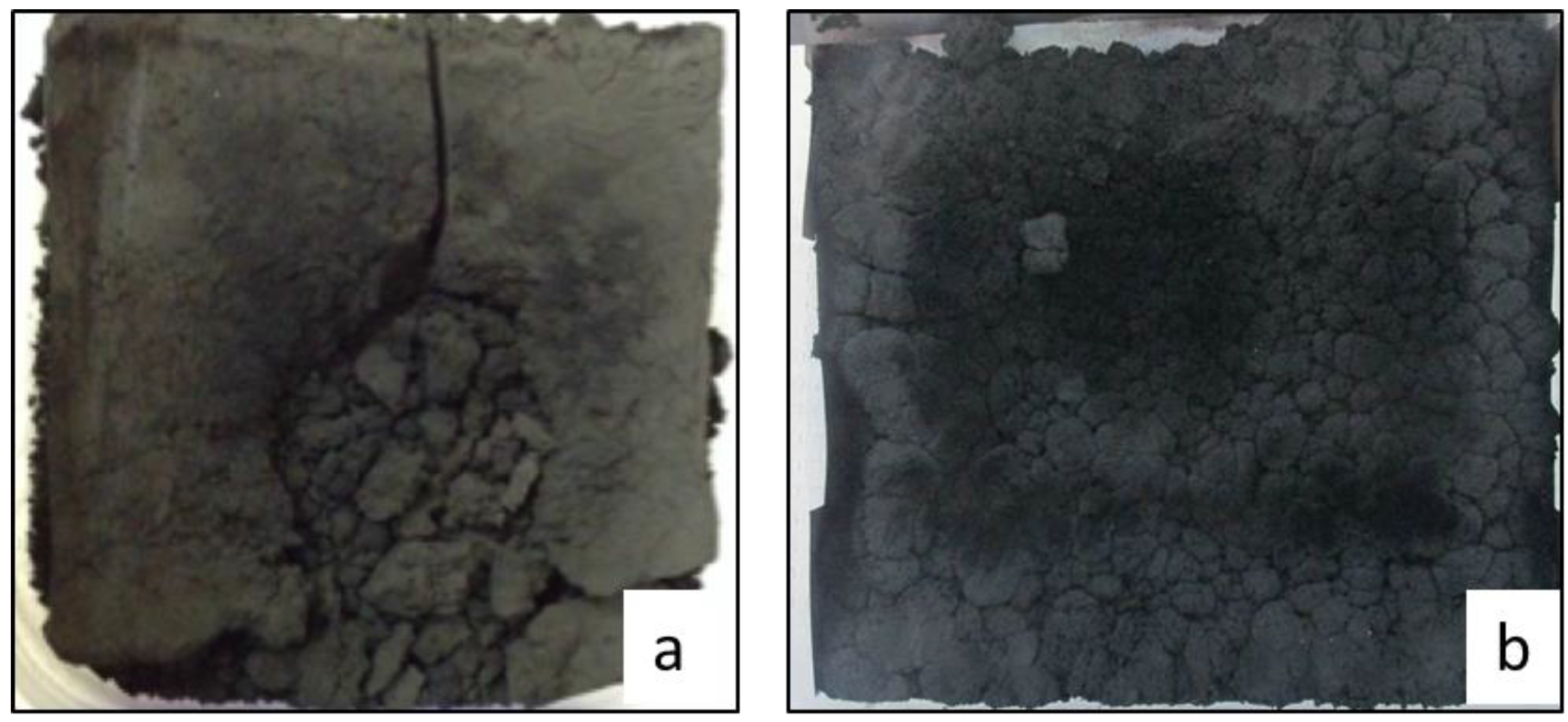
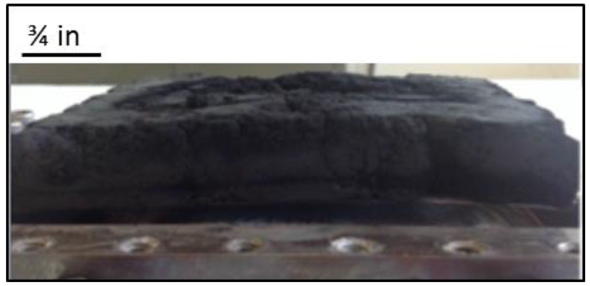
3.1. Growth Experiments

3.2. ANSYS Flow Models


3.3. Growth Model Based on Radical Species (GSD)

| Deflector | Catalyst (Pd) weight (g) | Gas flow (sccm) | Percent of chamber filled (%) | ||
|---|---|---|---|---|---|
| N2 | O2 | C2H4 | |||
| N/A | 0.680 | 100 | 15 | 15 | 33 |
| 2a | 0.500 | 300 | 45 | 45 | 55 |
| 2b | 0.510 | 300 | 45 | 45 | 60 |
| 2c | 0.508 | 300 | 45 | 45 | 75 |
| 2d | 0.501 | 300 | 45 | 45 | 60 |
| 2e | 0.503 | 300 | 45 | 45 | 85 |
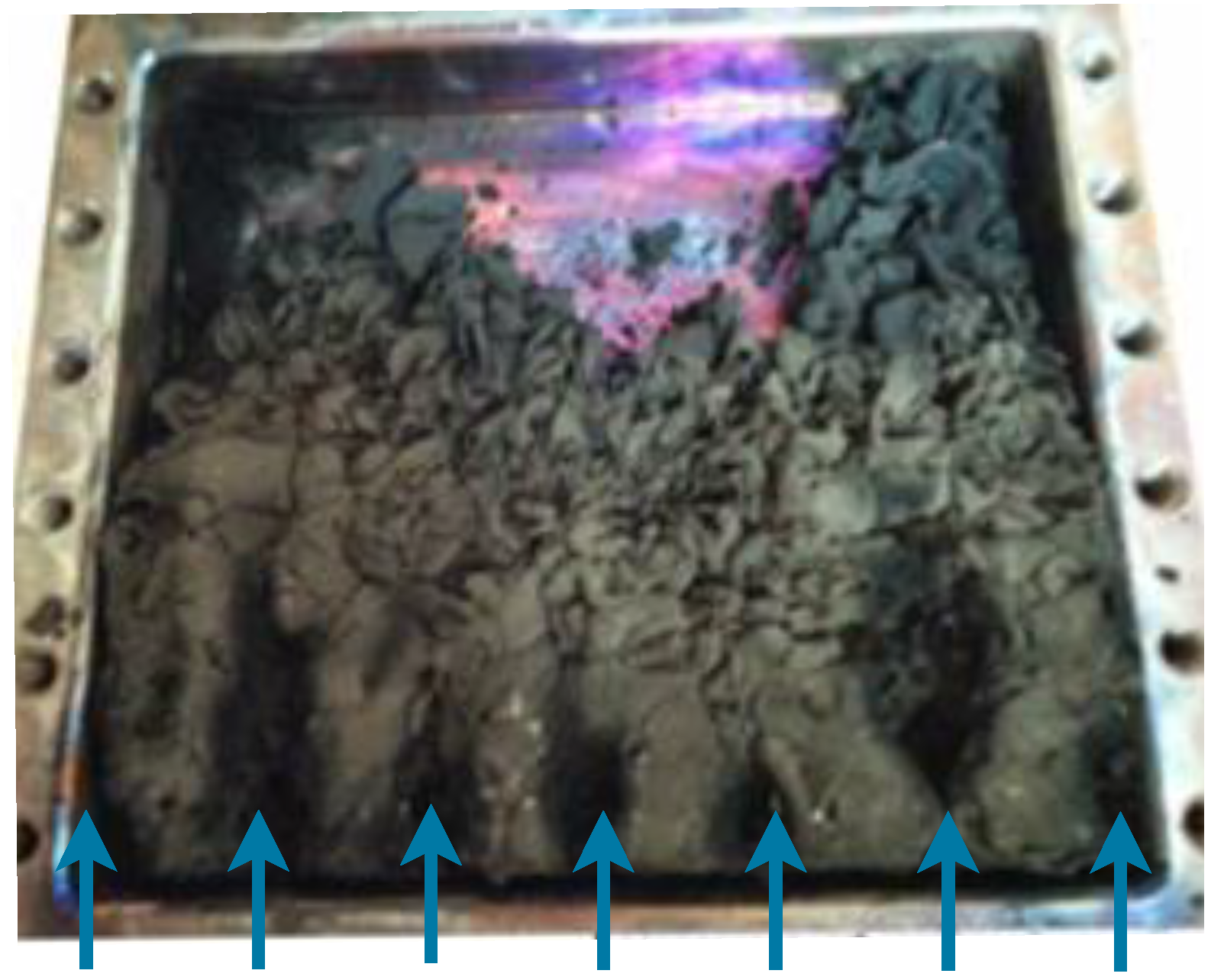
| 2f | 0.506 | 300 | 45 | 45 | 100 |


4. Conclusions
Acknowledgments
Author Contributions
Conflicts of Interest
References
- Dai, K.; Liang, C.; Dai, J.; Lu, L.; Zhu, G.; Liu, Z.; Liu, Q.; Zhang, Y. High-yield synthesis of carbon nanotube-porous nickel oxide nanosheet hybrid and its electrochemical capacitance performance. Mater. Chem. Phys. 2014, 143, 1344–1351. [Google Scholar] [CrossRef]
- Moon, J.; An, K.; Lee, Y.; Park, Y.; Bae, D.; Park, G. High-yield purification process of singlewalled carbon nanotubes. J. Phys. Chem. B 2001, 105, 5677–5681. [Google Scholar] [CrossRef]
- Park, Y.; Choi, Y.; Kim, K.; Chung, D.; Bae, D.; An, K.; Lim, S.; Zhu, X.; Lee, Y. High yield purification of multiwalled carbon nanotubes by selective oxidation during thermal annealing. Carbon 2001, 39, 655–661. [Google Scholar] [CrossRef]
- Wang, H.; Koleilat, G.I.; Liu, P.; Jimenez-Oses, G.; Lai, Y.; Vosgueritchian, M.; Fang, Y.; Park, S.; Houk, K.N.; Bao, Z. High-Yield Sorting of Small-Diameter Carbon Nanotubes for Solar Cells and Transistors. ACS Nano 2014, 8, 2609–2617. [Google Scholar] [CrossRef] [PubMed]
- Zhang, G.; Mann, D.; Zhang, L.; Javey, A.; Li, Y.; Yenilmez, E.; Wang, Q.; McVittie, J.; Nishi, Y.; Gibbons, J.; et al. Ultra-high-yield growth of vertical single-walled carbon nanotubes: Hidden roles of hydrogen and oxygen. Proc. Natl. Acad. Sci. USA 2005, 102, 16141–16145. [Google Scholar] [CrossRef] [PubMed]
- Hernandez, Y.; Nicolosi, V.; Lotya, M.; Blighe, F.M.; Sun, Z.; De, S.; McGovern, I.T.; Holland, B.; Byrne, M.; Gun’ko, Y.K.; et al. High-yield production of graphene by liquid-phase exfoliation of graphite. Nat. Nanotechnol. 2008, 3, 563–568. [Google Scholar] [CrossRef] [PubMed]
- Joung, D.; Chunder, A.; Zhai, L.; Khondaker, S.I. High yield fabrication of chemically reduced graphene oxide field effect transistors by dielectrophoresis. Nanotechnology 2010, 21. [Google Scholar] [CrossRef] [PubMed]
- Qian, W.; Hao, R.; Hou, Y.; Tian, Y.; Shen, C.; Gao, H.; Liang, X. Solvothermal-Assisted Exfoliation Process to Produce Graphene with High Yield and High Quality. Nano Res. 2009, 2, 706–712. [Google Scholar] [CrossRef]
- Wang, J.; Manga, K.K.; Bao, Q.; Loh, K.P. High-Yield Synthesis of Few-Layer Graphene Flakes through Electrochemical Expansion of Graphite in Propylene Carbonate Electrolyte. J. Am. Chem. Soc. 2011, 133, 8888–8891. [Google Scholar] [CrossRef] [PubMed]
- Knite, M.; Teteris, V.; Kiploka, A.; Kaupuzs, J. Polyisoprene-carbon black nanocomposites as tensile strain and pressure sensor materials. Sens. Actuators A Phys. 2004, 110, 142–149. [Google Scholar] [CrossRef]
- Karimov, K.S.; Saleem, M.; Karieva, Z.M.; Khan, A.; Qasuria, T.A.; Mateen, A. A carbon nanotube-based pressure sensor. Phys. Scr. 2011, 83. [Google Scholar] [CrossRef]
- Poveda, R.L.; Achar, S.; Gupta, N. Viscoelastic properties of carbon nanofiber reinforced multiscale syntactic foam. Compos. Part B Eng. 2014, 58, 208–216. [Google Scholar] [CrossRef]
- Tibbetts, G.G.; Lake, M.L.; Strong, K.L.; Rice, B.P. A review of the fabrication and properties of vapor-grown carbon nanofiber/polymer composites. Compos. Sci. Technol. 2007, 67, 1709–1718. [Google Scholar] [CrossRef]
- Luhrs, C.; Daskam, C.; Jonathan, E.P.G. Fabrication of a Low Density Carbon Fiber Foam and Its Characterization as a Strain Gauge. Materials 2014, 7, 3699–3714. [Google Scholar] [CrossRef] [Green Version]
- Atwater, M.A.; Mousavi, A.K.; Leseman, Z.C.; Phillips, J. Direct synthesis and characterization of a nonwoven structure comprised of carbon nanofibers. Carbon 2013, 57, 363–370. [Google Scholar] [CrossRef]
- Chawla, S.; Naraghi, M.; Davoudi, A. Effect of twist and porosity on the electrical conductivity of carbon nanofiber yarns. Nanotechnology 2013, 24. [Google Scholar] [CrossRef] [PubMed]
- Ebbesen, T.; Lezec, H.; Hiura, H.; Bennett, J.; Ghaemi, H.; Thio, T. Electrical conductivity of individual carbon nanotubes. Nature 1996, 382, 54–56. [Google Scholar] [CrossRef]
- Inagaki, M.; Qiu, J.; Guo, Q. Carbon foam: Preparation and application. Carbon 2015, 87, 128–152. [Google Scholar] [CrossRef]
- Silverman, E. Multifunctional carbon foam development for spacecraft applications. SAMPE J. 2005, 41, 19–23. [Google Scholar]
- Gallego, N.; Klett, J. Carbon foams for thermal management. Carbon 2003, 41, 1461–1466. [Google Scholar] [CrossRef]
- Rogers, D.; Plucinski, J.; Stansberry, P.; Stiller, A.; Zondlo, J. Low-Cost Carbon Foams for Thermal Protection and Reinforcement Applications; Society for the Advancement of Material and Process Engineering: Lonh Beach, CA, USA, 2000. [Google Scholar]
- Zhang, Q.; Zhou, X.; Yang, H. Carbon foam materials prepared from polyacrylonitrile and their application in electrochemical capacitors. Acta Polym. Sin. 2003, 1, 749–753. [Google Scholar]
- Chen, C.; Kennel, E.; Stiller, A.; Stansberry, P.; Zondlo, J. Carbon foam derived from various precursors. Carbon 2006, 44, 1535–1543. [Google Scholar] [CrossRef]
- Yang, X.; He, P.; Xia, Y. Preparation of mesocellular carbon foam and its application for lithium/oxygen battery. Electrochem. Commun. 2009, 11, 1127–1130. [Google Scholar] [CrossRef]
- Glenk, F.; Schirmer, M.; Guetlein, S.; Etzold, B. Synthesis of microporous Carbon Foams for Catalytic Applications. Chem. Ing. Tech. 2010, 82, 897–903. [Google Scholar]
- Phillips, J.; Shiina, T.; Nemer, M.; Lester, K. Graphitic structures by design. Langmuir 2006, 22, 9694–9703. [Google Scholar] [CrossRef] [PubMed]
- Phillips, J.; Leseman, Z.C.; Cordaro, J.; Luhrs, C. Novel Graphitic Structures by Design. In Proceedings of the ASME 2007 International Mechanical Engineering Congress and Exposition, Seattle, WA, USA, 11–15 November 2007.
- Wu, N.; Phillips, J. Reaction-Enhanced Sintering of Platinum Thin-Films during Ethylene Oxidation. J. Appl. Phys. 1986, 59, 769–779. [Google Scholar] [CrossRef]
- Wu, N.; Phillips, J. Catalytic Etching of Platinum during Ethylene Oxidation. J. Phys. Chem. 1985, 89, 591–600. [Google Scholar] [CrossRef]
- Baker, R.T.K.; Barber, M.A.; Waite, R.J.; Harris, P.S.; Feates, F.S. Nucleation and Growth of Carbon Deposits from Nickel Catalyzed Decomposition of Acetylene. J. Catal. 1972, 26, 51–62. [Google Scholar] [CrossRef]
- Gavillet, J.; Loiseau, A.; Journet, C.; Willaime, F.; Ducastelle, F.; Charlier, J. Root-growth mechanism for single-wall carbon nanotubes. Phys. Rev. Lett. 2001, 87. [Google Scholar] [CrossRef] [PubMed]
- Gavillet, J.; Loiseau, A.; Ducastelle, F.; Thair, S.; Bernier, P.; Stephan, O.; Thibault, J.; Charlier, J. Microscopic mechanisms for the catalyst assisted growth of single-wall carbon nanotubes. Carbon 2002, 40, 1649–1663. [Google Scholar] [CrossRef]
- Saito, Y.; Okuda, M.; Fujimoto, N.; Yoshikawa, T.; Tomita, M.; Hayashi, T. Single-Wall Carbon Nanotubes Growing Radially from Ni Fine Particles Formed by Arc Evaporation. Jpn. J. Appl. Phys. Part 2 Lett. Express Lett. 1994, 33, L526–L529. [Google Scholar] [CrossRef]
- Frenklach, M. Reaction mechanism of soot formation in flames. Phys. Chem. Chem. Phys. 2002, 4, 2028–2037. [Google Scholar] [CrossRef]
- Atwater, M.A.; Phillips, J.; Doorn, S.K.; Luhrs, C.C.; Fernandez, Y.; Menendez, J.A.; Leseman, Z.C. The production of carbon nanofibers and thin films on palladium catalysts from ethylene-oxygen mixtures. Carbon 2009, 47, 2269–2280. [Google Scholar] [CrossRef]
- Atwater, M.A.; Phillips, J.; Leseman, Z.C. The effect of powder sintering on the palladium-catalyzed formation of carbon nanofibers from ethylene-oxygen mixtures. Carbon 2010, 48, 1932–1938. [Google Scholar] [CrossRef]
- Smith, P.; Cashman, J. ANSYS-Computational Fluid Dynamics (CFD) Software; Ansys, Inc.: Cecil Township, PA, USA, 2015. [Google Scholar]
- Sarioğlan, Ş. Recovery of palladium from spent activated carbon-supported palladium catalysts. Platin. Met. Rev. 2013, 57, 289–296. [Google Scholar]
- Levenspiel, O. Chemical Reaction Engineering; Wiley India: New Delhi, India, 2007. [Google Scholar]
- Fogler, H.S. Elements of Chemical Reaction Engineering; Prentice Hall PTR: Upper Saddle River, NJ, USA, 2006. [Google Scholar]
- Baker, R.T.K.; Yates, D.J.C.; Dumesic, J.A. Filamentous Carbon Formation over Iron Surfaces. ACS Symp. Ser. 1982, 202, 1–21. [Google Scholar]
- Walker, P.L.; Thrower, P.A. Chemistry and Physics of Carbon; Marcel Dekker: New York, NY, USA, 1978. [Google Scholar]
- Luhrs, C.C.; Garcia, D.; Tehrani, M.; Al-Haik, M.; Taha, M.R.; Phillips, J. Generation of carbon nanofilaments on carbon fibers at 550 °C. Carbon 2009, 47, 3071–3078. [Google Scholar] [CrossRef]
- Forsythe, W.E. Smithsonian Physical Tables, 9th Revised ed.; Knovel; Table 282. Density of Various Solids; Knovel: Norwich, NY, USA, 2003. [Google Scholar]
- Wu, N.; Phillips, J. Carbon Deposition on Platinum during Ethylene Oxidation. J. Catal. 1988, 113, 383–397. [Google Scholar] [CrossRef]
- Atwater, M.A.; Phillips, J.; Leseman, Z.C. Formation of Carbon Nanofibers and Thin Films Catalyzed by Palladium in Ethylene-Hydrogen Mixtures. J. Phys. Chem. C 2010, 114, 5804–5810. [Google Scholar] [CrossRef]
- Rasband, W.S. Image J Homepapge. National Institutes of Health: Bethesda, MD, USA. Available online: http://imagej.nih.gov/ij/ (accessed on 2 November 2015).
© 2016 by the authors; licensee MDPI, Basel, Switzerland. This article is an open access article distributed under the terms and conditions of the Creative Commons by Attribution (CC-BY) license (http://creativecommons.org/licenses/by/4.0/).
Share and Cite
Curtin, W.; Arias-Monje, P.J.; Dominguez, C.; Phillips, J.; Luhrs, C.C. Scaling up the Fabrication of Mechanically-Robust Carbon Nanofiber Foams. Fibers 2016, 4, 9. https://doi.org/10.3390/fib4010009
Curtin W, Arias-Monje PJ, Dominguez C, Phillips J, Luhrs CC. Scaling up the Fabrication of Mechanically-Robust Carbon Nanofiber Foams. Fibers. 2016; 4(1):9. https://doi.org/10.3390/fib4010009
Chicago/Turabian StyleCurtin, William, Pedro J. Arias-Monje, Charliean Dominguez, Jonathan Phillips, and Claudia C. Luhrs. 2016. "Scaling up the Fabrication of Mechanically-Robust Carbon Nanofiber Foams" Fibers 4, no. 1: 9. https://doi.org/10.3390/fib4010009